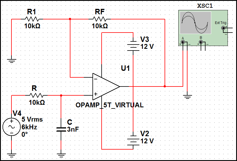
First Order Low Pass Filter Circuit Diagram
The current’s amplitude varies between zero and 20 volts. A tutorial on the basics of passive rc filters;
Firstorder butterworth active Lowpass filter circuit
First Order Low Pass Filter Circuit Diagram. Cascading together they form a second order low. R1 c1 is first order and r2 c2 is second order. The current’s amplitude varies between zero and 20 volts.
Web As An Example, A Simple Integrator Is Shown In Figure \(\Pageindex{1}\).
Web 3 cro probes cro (cathods ray oscilloscope). Web the circuit diagram of the single pole or first order active low pass filter is shown below. The order of a filter is.
What Is A Low Pass Filter?
R1 c1 is first order and r2 c2 is second order. A tutorial on the basics of passive rc filters; The current’s amplitude varies between zero and 20 volts.
Cascading Together They Form A Second Order Low.
1 (a) and its frequency response characteristics is shown in fig.

First Order Low Pass Filter(हिन्दी ) YouTube
1st order low pass filter Multisim Live

Passive Low Pass Filters EEE Parts Database
Low Pass Filter (First Order) Multisim Live

Firstorder butterworth active Lowpass filter circuit

current Transfer function and weird assumption in circuit

First Order Butterworth Low Pass Filter Expression for gain and

Solved You are designing a first order low pass filter with
