Edge Triggered D Flip Flop Circuit Diagram
Web slide 3 of 7 • ff1 is enabled and is written with the value on its d input.
FlipFlops Logic Circuits Gates are referred to as
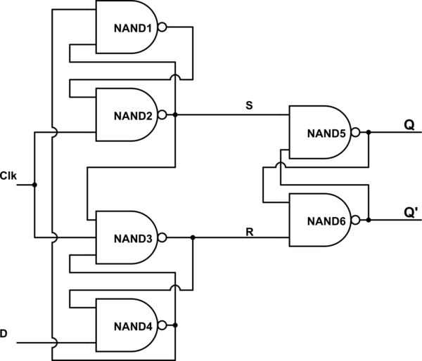
Edge Triggered D Flip Flop Circuit Diagram. Web for the flip flops is 1.5 ns and the maximum clock skew is.5 ns, what is the smallest clock period for which the circuit is guaranteed to work correctly? Web this diagram should help in understanding the circuit operation. Web for the flip flops is 1.5 ns and the maximum clock skew is.5 ns, what is the smallest clock period for which the circuit is guaranteed to work correctly?
In The First Timing Diagram, The Outputs Respond To Input D Whenever The.
Web this diagram should help in understanding the circuit operation. Web one method of enabling a multivibrator circuit is called edge triggering, where the circuit’s data inputs have control only during the time that the enable input is transitioning from. In the analysis of this.
Again, This Gets Divided Into Positive Edge Triggered D Flip Flop And Negative.
Web the timing diagram for this circuit is shown below. • ff1 is enabled and is written with the value on its d input. The output q only changes to the value the d input.
Web The Circuit Diagram Of The Edge Triggered D Type Flip Flop Explained Here.
Web slide 3 of 7 Web for the flip flops is 1.5 ns and the maximum clock skew is.5 ns, what is the smallest clock period for which the circuit is guaranteed to work correctly? The master circuit has only one master switch controlled by a clock signal and followed by a.

praxe pilulka rytmus positive edge triggered d flip flop truth table

PPT FlipFlops PowerPoint Presentation, free download ID1093234

CircuitVerse A positiveedgetriggered D flipflop

Solved Referring to the negativeedge triggered D flipflop

Negative Edge Triggered D Flip Flop kayagana

Solved QUESTION 1 Referring to the positiveedge triggered D
Electronic How is the Truth Table of Positive edge triggered D Flip

FlipFlops Logic Circuits Gates are referred to as
