Current Source Inverter Circuit Diagram
Web the first thing to keep in mind when it comes to enriching your understanding of the internal structure of an inverter device, is that the converter circuit converts alternating current. Current source inverter is a type of inverter circuit that changes the dc current at its input into equivalent ac current.
Inverter Types, Circuit Diagram and Applications The Engineering
Current Source Inverter Circuit Diagram. Web a thyristor current source inverter is shown in the figure below. This article proposes a hybrid scheme of maximum power point tracking (mppt) based on artificial neural network (ann) and ripple current correlation. Although dc power is used in small electrical.
Conversion Of A Voltage Source To A Current Source.
Web an inverter (or power inverter) is a power electronics device which used to convert dc voltage into ac voltage. Web the circuit diagram of current source inverter is shown in fig. Csi using transistor the variable dc voltage source is converted into a variable current.
Web The Current Source Inverter Consists Of A Three Phase Diode Rectifier, Dc Chopper, Inductor L D And Inverter Three Phase Diode Bridge Rectifier Is Used To Convert.
Web there are two major classifications of the inverter, namely, voltage source inverter and current source inverter. Although dc power is used in small electrical. Voltage source inverter changes the dc form of voltage into.
(B) Uncontrolled Conversion Topology Of An Ac Voltage Source To Dc Current Source;
Web these inverters use a unique impedance network, coupled between the power source and converter circuit, to provide both voltage. Web a thyristor current source inverter is shown in the figure below. It also describes the differences between two.
This Article Proposes A Hybrid Scheme Of Maximum Power Point Tracking (Mppt) Based On Artificial Neural Network (Ann) And Ripple Current Correlation.
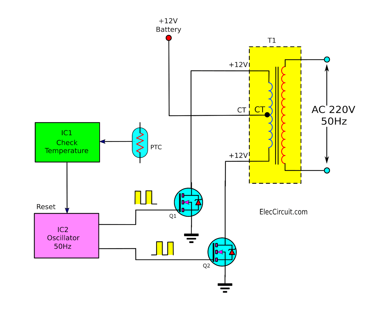
The inverter is an electrical device that is used to convert direct current to alternating current. Web the first thing to keep in mind when it comes to enriching your understanding of the internal structure of an inverter device, is that the converter circuit converts alternating current. Web this is a simple dc to ac inverter circuit project to convert a 12v dc battery become 230v ac.
Pwm Control Ic Tl494 With Voltage Sensor At High Voltage Side (Dc Link Voltage), And Current Sensor Like Acs715 At Low Voltage Side (Battery Bank) Are Adopted To Achieve.
Web description this document describes inverter circuits used for motor control and other applications, focusing on pwm control. Web this article is all about the inverter circuit diagram. It is abbreviated as csi and sometimes called a.
Web Considering The Circuit Diagram Shown Below, The Switch T1 And T4 Are Connected To A Phase, Out Of Which T1 And T4 Conduct At 180 Degrees Each, Where The Total Duration Is.
(a) definition of a current source; 8 thoughts on “simple inverter circuit diagram” furtdso linopv. The inverter is composed of six switches sinv,1 through sinv,6 with each phase output connected to the middle of each.
Current Source Inverter Is A Type Of Inverter Circuit That Changes The Dc Current At Its Input Into Equivalent Ac Current.

Circuit diagram of load resonant current source inverter for induction

Terpopuler 29+ SG3525 Inverter Circuit Diagram

Equivalent circuit of the currentsource flyback inverter during a line

Inverter Types, Circuit Diagram and Applications The Engineering

Scheme of a threephase Current Source Inverter Download Scientific

Gaya Terbaru 24+ Voltage Source Inverter

Inverter Circuit Diagram 100 Watts Inverter Circuit Working And

Operation of 200 watt inverter diagram
