12V And 5V Dual Power Supply Circuit Diagram
The circuit includes the voltage regulator. Web table of contents hide how to choose a 5v converter 5v zener diode regulator—lower 50ma 100ma 5v converter circuit 200ma, 5v regulator 500ma, 5v.
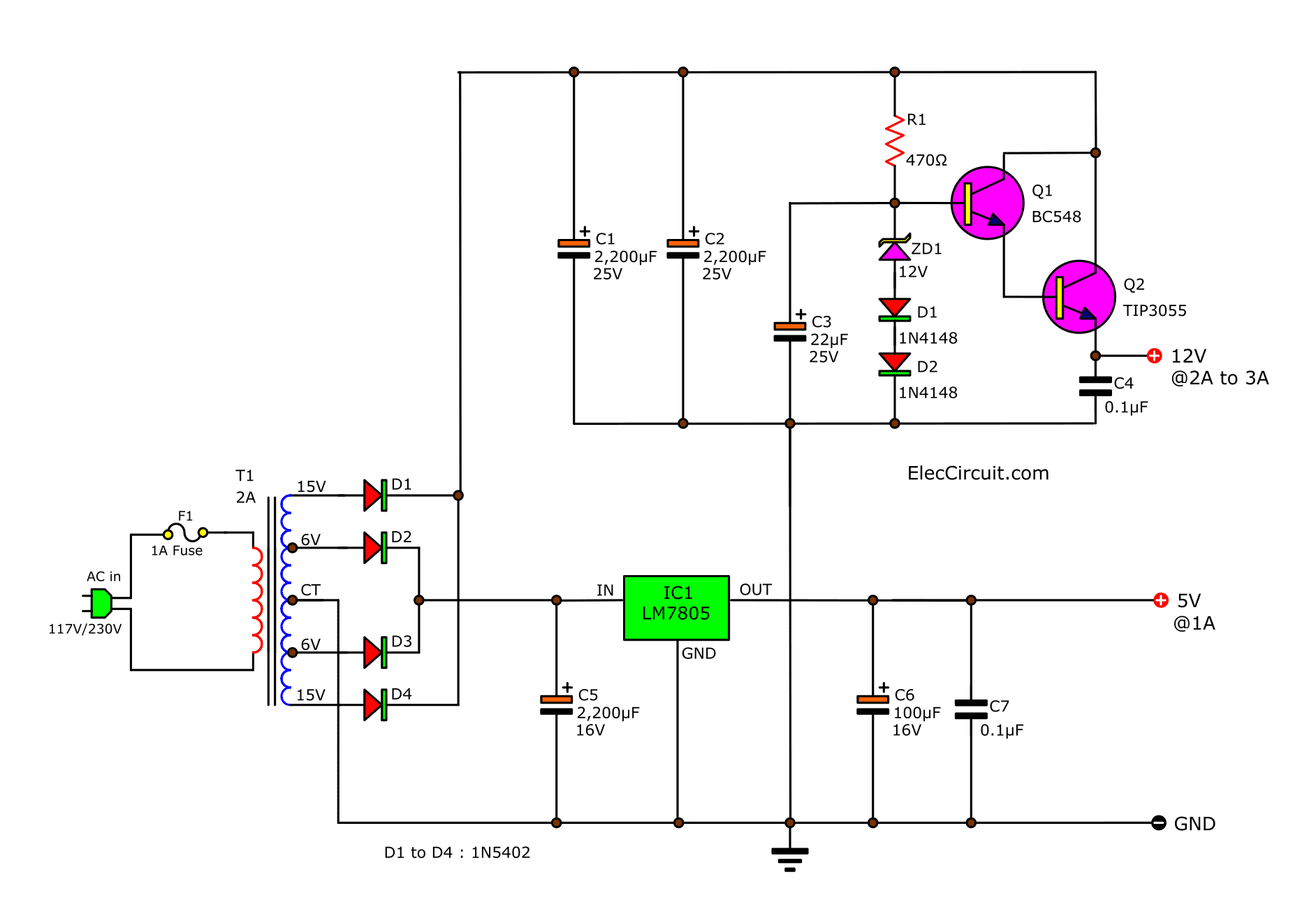
Many ideas of 12V and 5V Dual Power Supply Circuit Diagram at 3A max
12V And 5V Dual Power Supply Circuit Diagram. Shiwakiffmy shiwaki ac dc 85 265v to 12v 5v dual output step. Generally 12v dc or 15 v dc dual suppply used. Generally 12v dc or 15 v dc dual suppply used.
Web 12V And 5V Dual Power Supply.
Web the 12v and 5v dual power supply circuit diagram is given below: The outer two terminals of the centre tapped transformer are connected to the bridge rectifier circuit. Web dual power supply required to operate some circuit.
Web In This Post, We'll Explore 12V And 5V Dual Power Supply Circuit Diagrams, Including Their Principles Of Operation, Types, Components, And Applications.
Web circuit diagram with parts list. The circuit includes the voltage regulator. Dual power supplies are circuits that generate two different output voltages from a single input source.
Web Basically, The Power Supply Is The Circuit That Converts The Alternating Current Power Into Direct Current Power.
Web circuit diagram working explanation here there are three circuits available. Usually the 12v side is. One of the most common.
Converting 12V Ac Into 12V Dc Using Full Bridge Rectifier.
There are numerous types and configurations. Here is complete circuit diagram of dual power supply. 12v 5v dual power supply circuit diagram 3a max eleccircuit.
Web Table Of Contents Hide How To Choose A 5V Converter 5V Zener Diode Regulator—Lower 50Ma 100Ma 5V Converter Circuit 200Ma, 5V Regulator 500Ma, 5V.
Web the diagram above shows how a simple yet higher versatile, adjustable dual power supply circuit could be built through just a couple of lm317 ics. The transformer t1 can be a 230v primary, 15v secondary, 1a. Web here we designed a simple 5v dual power supply circuit by using icl7660.
Shiwakiffmy Shiwaki Ac Dc 85 265V To 12V 5V Dual Output Step.
Converting 220v ac into 12v ac using step down transformer the primary terminals of. Generally 12v dc or 15 v dc dual suppply used. The only;y difference is the output voltage happens because of the different.
Web 12V Dual Power Supply Circuit Diagram With Explanation #12V_Dual_Power_Supply_Circuit_Diagram_With_Explanation Tutorials For.
Connect the power supply to your circuit and power it up! Assemble the circuit on a good quality pcb or common board. Working explanation the circuit provides regulated dc output after processing the input.
Constructing Dual Power Supply Circuit:
I personally use the power supply as a tool for basic testing. Web led 1 indicates the 12v dc supply presence. 12 volt dc is again filtered by c3 capacitor and then regulated by ic l7805 regulator, at the output of 7805 we can.

12V & 5V Dual Power Supply

My Room schematic diagram power supply dual output, 12V & 5V

12v And 5v Dual Power Supply Circuit IOT Wiring Diagram

Many ideas of 12V and 5V Dual Power Supply Circuit Diagram at 3A max

Quester 12V and 5V dual constant power supply

12v And 5v Dual Power Supply Circuit IOT Wiring Diagram
Many ideas of 12V and 5V Dual Power Supply Circuit Diagram at 3A max

12V & 5V Dual Power Supply
